CSIT_Labs
Lab 6
OBJECTIVE
TO VERIFY TRUTH TABLE OF MULTIPLEXER(1:8) AND DEMULTIPLEXER(8:1) via SIMULATOR
APPARATUS REQUIRED
Simulator
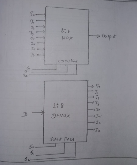
BLOCK DIAGRAM OF 1:8 MULTIPLEXER AND DEMULTIPLEXER
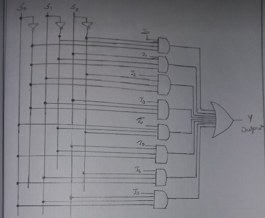
Circuit Diagram of Multiplexer
Function Table of Multiplexer
| Inputs | Output | ||
|---|---|---|---|
| S0 | S1 | S2 | Y |
| 0 | 0 | 0 | I0 |
| 0 | 0 | 1 | I1 |
| 0 | 1 | 0 | I2 |
| 0 | 1 | 1 | I3 |
| 1 | 0 | 0 | I4 |
| 1 | 0 | 1 | I5 |
| 1 | 1 | 0 | I6 |
| 1 | 1 | 1 | I7 |
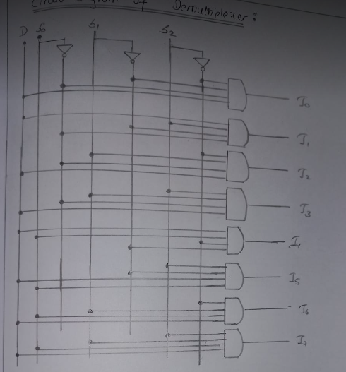
Circuit Diagram of Demultiplexer
Function Table of Demultiplexer
| D | Select | Outputs | |||||||||
|---|---|---|---|---|---|---|---|---|---|---|---|
| S0 | S1 | S2 | I0 | I1 | I2 | I3 | I4 | I5 | I6 | I7 | |
| 1 | 0 | 0 | 0 | 1 | 0 | 0 | 0 | 0 | 0 | 0 | 0 |
| 1 | 0 | 0 | 1 | 0 | 1 | 0 | 0 | 0 | 0 | 0 | 0 |
| 1 | 0 | 1 | 0 | 0 | 0 | 1 | 0 | 0 | 0 | 0 | 0 |
| 1 | 0 | 1 | 1 | 0 | 0 | 0 | 1 | 0 | 0 | 0 | 0 |
| 1 | 1 | 0 | 0 | 0 | 0 | 0 | 0 | 1 | 0 | 0 | 0 |
| 1 | 1 | 0 | 1 | 0 | 0 | 0 | 0 | 0 | 1 | 0 | 0 |
| 1 | 1 | 1 | 0 | 0 | 0 | 0 | 0 | 0 | 0 | 1 | 0 |
| 1 | 1 | 1 | 1 | 0 | 0 | 0 | 0 | 0 | 0 | 0 | 1 |
Simulator diagram of Multiplexer
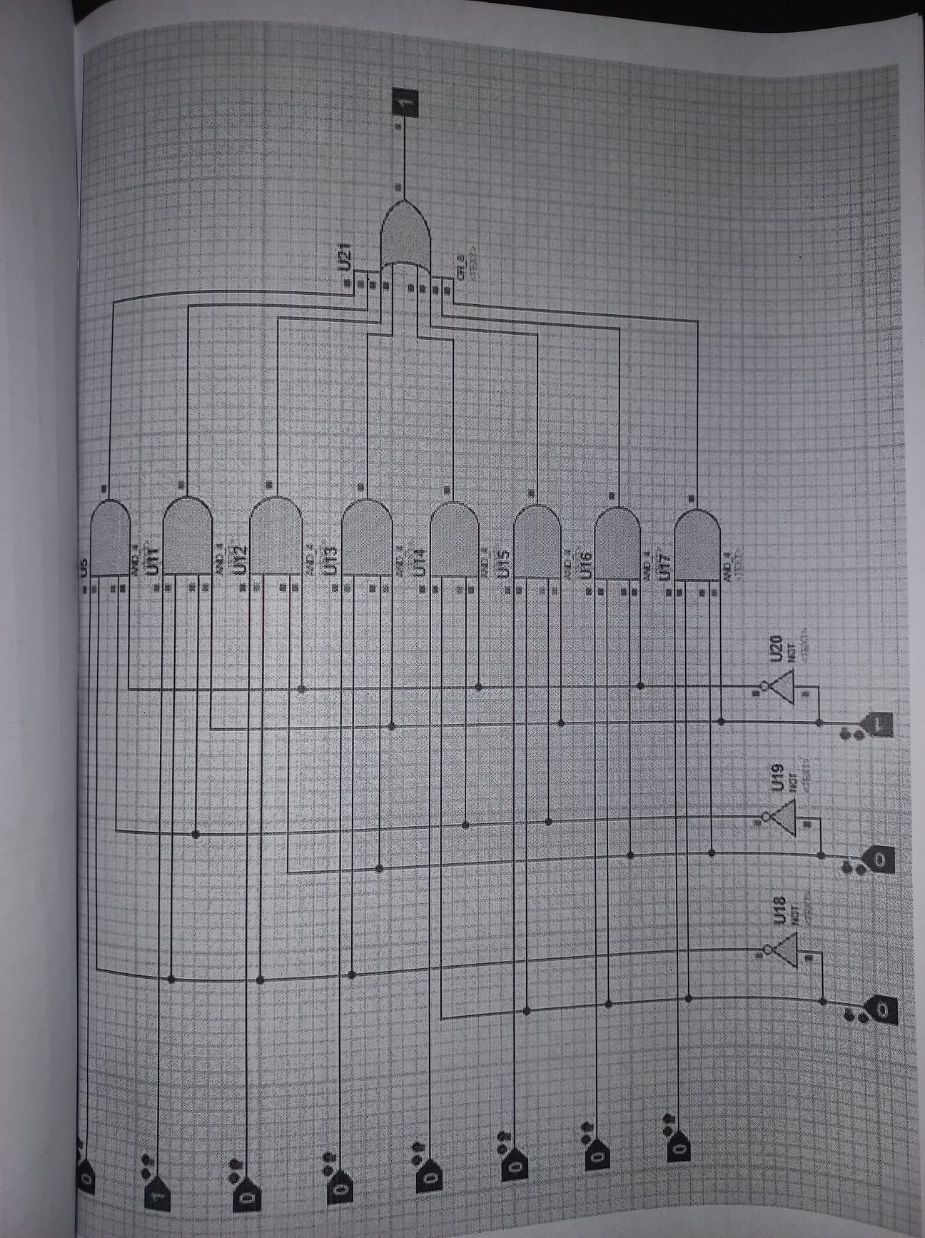
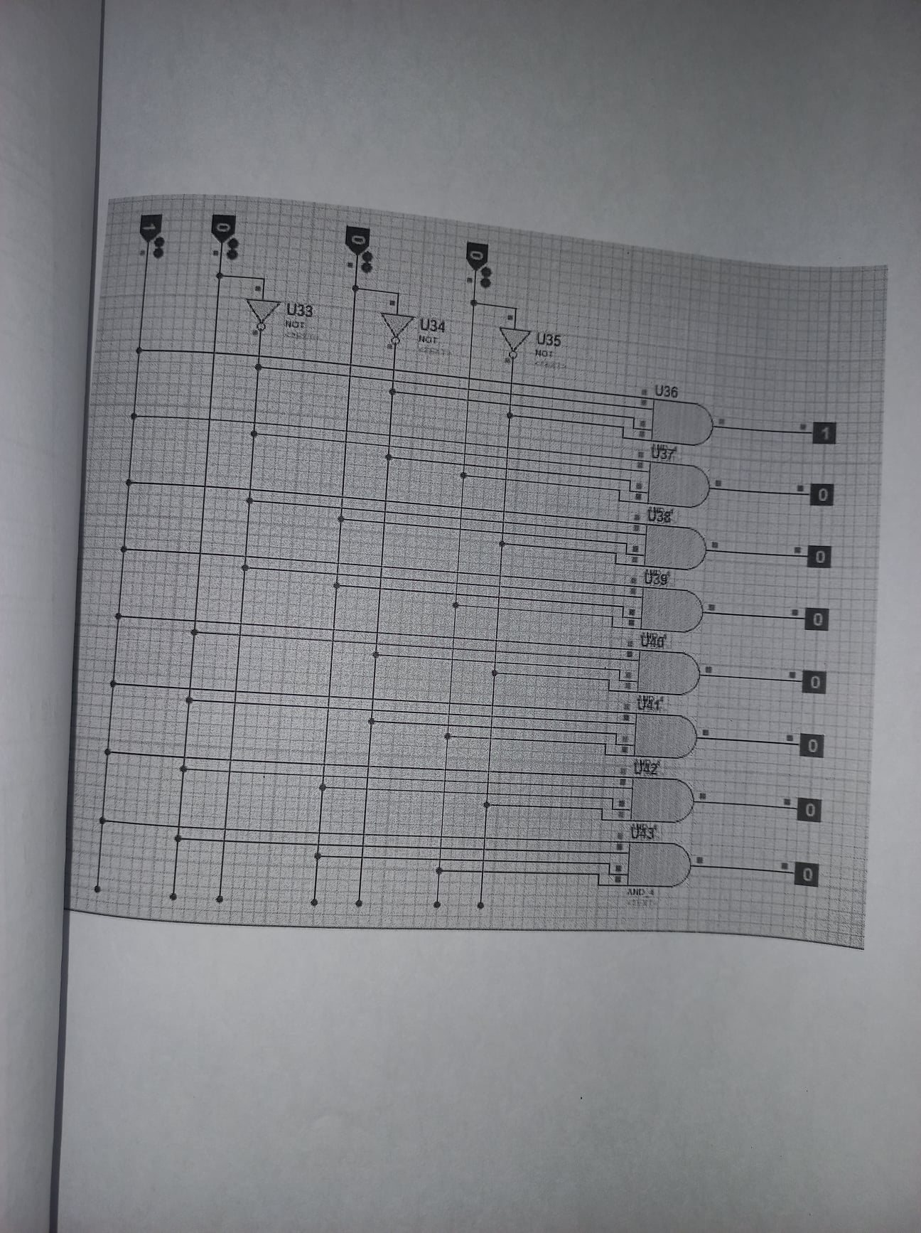
Simulator diagram of DeMultiplexer
RESULT
The truth table of Multiplexer and Demultiplexer is verified.